China Wuxi Arta Precision Technology Co.,Ltd.
Wuxi Arta Precision Technology Co.,Ltd.
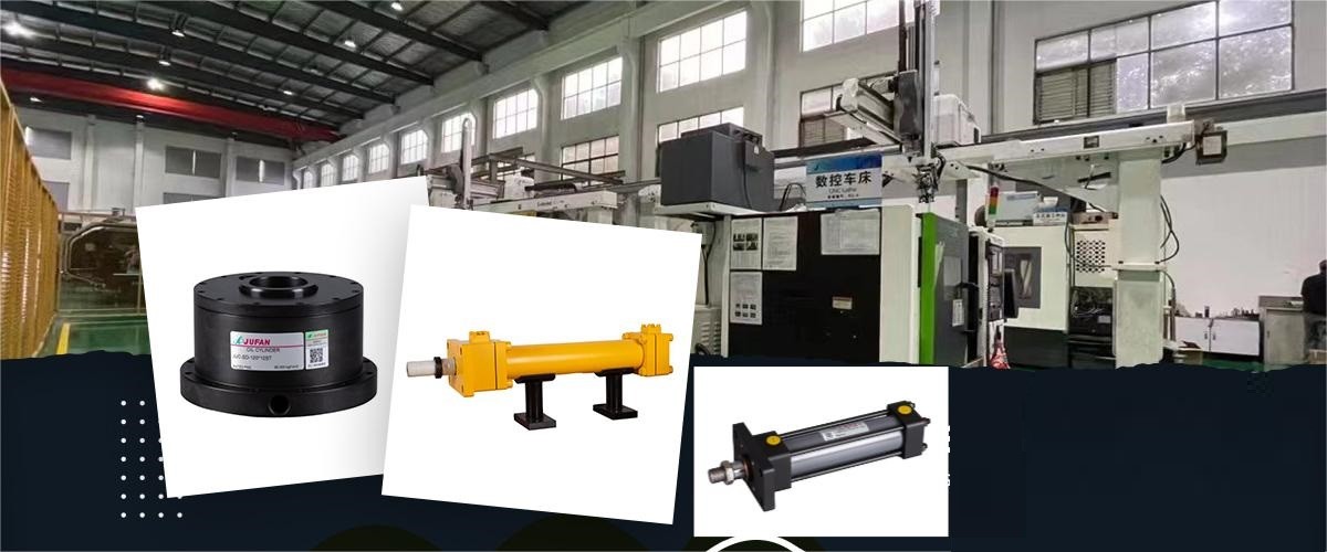
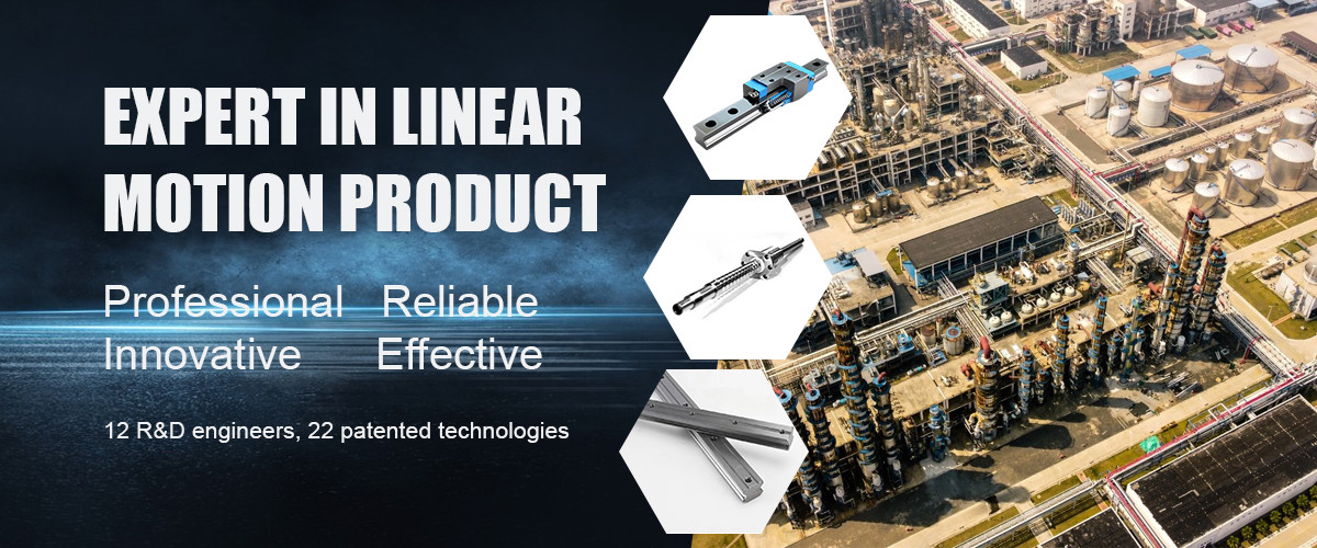
The factory was established in June 1979, has been in automation industry for more than 25 years and now is one of major makers to produce pneumatic, hydraulic, and vacuum related products and to serve as system integrator of fluid power and transmission control fields.We devote to research and professional manufacturing in the field of linear motion components . Our Main products are consist of ball screw, linear guide, linear guide, ball screw linear guide rail module,and hydrauic oil ...
Learn More
Request A Quote
No. of Employees:
0+
Year Established:
Export p.c:
0%
customers served
0
WE PROVIDE
THE BEST SERVICE!
You can contact us in various ways
CONTACT US
Fax
WhatsApp
8613057223323
Skype
Wechat
+8613057223323

quality Linear Guide Rail & Ball Linear Guideway factory

Aluminum Knife Punch Air Cylinder Vertical Mounting Output Capacity 110CC Video

Aluminum Knife Punch Air Cylinder Vertical Mounting Output Capacity 110CC

Name:Knife Punch Air Cylinder

Diameter:Ø100

Mounting:Vertical

Get Best Price
Supercharged Knife Punch Air Cylinder Working Temperature 0ºC-60ºC  Knife To Knife Exchange Super Fast Video

Supercharged Knife Punch Air Cylinder Working Temperature 0ºC-60ºC Knife To Knife Exchange Super Fast

Name:High-Speed Knife Punch Air Cylinder

Working Temperature:0ºC - 60ºC

Mounting:Directly Mounted Onto The Main Shaft

Get Best Price
Air Oil Unclamping Booster Pneumatic Cylinder Diameter 12:ø125 Pressure Boosting Ratio 11:1/30:1 Video

Air Oil Unclamping Booster Pneumatic Cylinder Diameter 12:ø125 Pressure Boosting Ratio 11:1/30:1

Name:Air Oil Unclamping Booster

Pneumatic Cylinder Diameterperature:12:Ø125

Pressure Boosting Ratio:11:1/30:1/12.7:1/39:1

Get Best Price
Oil Unclamping Cylinder Diameter High Clamping Force And Precision Video

Oil Unclamping Cylinder Diameter High Clamping Force And Precision

Name:Pneumatic Unclamping Cylinder

Pressure:0.4Mpa--0.6Mpa Aire Filtering And Compressed

Knife Exchange:Knife To Knife Change In 1second

Get Best Price
WHAT CUSTOMERS SAYS
Joseph Gorden
2023-08-29 17:05:00
Hi,Thank you a lot.Our guy could easily operate and it makes our machine running smoothly.
Chris Tucker
2023-08-29 16:59:53
Yes,of course.I literally had a nice time touring your factory.What most impresses me is your production management,it's perfect,your design and operation way can fit very well in our CNC machines.
Bellal Jackson
2023-08-29 17:03:50
Your company culture and your copperation before placing order really impressed me,expect future cooperaion in more feilds as now we are considering expand our business to establish new factory.
news View More
How to choose a cylinder actuator?
What is a cylinder actuator? A cylinder actuator is a mechanical device that converts compressed air or fluid power into motion, driving linear movement with precision. It's essential in automation, enabling machinery to push, pull, lift, or press with controlled force. Intrigued by how this technology powers modern industry? Discover the intricate workings of cylinder actuators and their pivotal role in our next segment.   After determining the application that requires a hydraulic linear actuator, you must consider several factors before selecting the ideal actuator. The planning and design process is vital for operating an efficient hydraulic operation, and the primary elements in the process include:   Calculating Mass: The mass of the object being lifted by hydraulics affects the size and durability of the cylinders.   Determining the physics involved: Are hydraulics needed for a simple pressing operation, or does it involve more complex movements?   Calculating the bore size: Larger barrels can accommodate applications that require significant force and torque.   Selecting the rod size: The length of the cylinder stroke, the bearing load and the rod buckling strength can help determine the appropriate rod size. If standard cylinders are unusable with the bore size, custom cylinders can be manufactured for the ideal fit.   Examining the cushion options: If the hydraulic application requires the cylinder rods to move at high speeds, cushioning can be used at either cylinder end to dampen the impact.
2023-10-16
Single acting cylinders VS double acting cylinder
There are many types of hydraulic cylinders for sale, with these being the four most common: SINGLE-ACTING CYLINDERS Single acting hydraulic cylinders produce power when hydraulic fluid enters a single port and flows into the cylinder and causes the cylinder to retract. Also called push cylinders, they feature a single-acting piston that moves in one direction and requires a motor or spring to reset its position.   DOUBLE-ACTING CYLINDERS In double acting hydraulic cylinder models, fluid moves into one port and exits through a second port, forcing the cylinder to retract and extend. With two pressurized chambers, double-acting pistons do not require a spring or motor to operate.   Hydraulic equipment and machines utilize single-acting and double-acting cylinders, and each type has its advantages. Single-acting cylinders are simpler and easier to maintain than double-acting cylinders. However, with more fluid in the pressurized chamber, double-acting actuators are easier for an operator to control.
2023-09-29
We are here: CIIF China International Induetry Fair 2023
The 23rd session China International Industry Fair will be held from 19th--23rd September 2023,whihc located in National Exhibition and Convention Center of Shanghai City.   We are in Hall-5,booth number 5.1-C037.   Expect your visit!  
2023-09-13
What do you know about ball screw transmission ?
Here's the translation of your text:   "The transmission mechanism of a ball screw uses rigid balls as intermediate elements between the screw and the nut, transforming sliding friction into rolling friction for transmission.   Both the screw and the nut have helical grooves on their surfaces with curved profiles. The combination of these two curved grooves forms a raceway. Inside the nut, there are multiple ball bearings, resulting in rolling friction between the screw and the nut. At both ends of the grooves in the nut, there are ball return tubes that allow balls to exit one end of the helical groove in the nut and return along the tube to the other end of the raceway. As a result, when the ball screw rotates relative to the nut, it undergoes continuous rolling motion within the helical raceway.   Ball screw transmission offers the following advantages:   High transmission efficiency: The transmission efficiency of ball screw transmission is generally between 92% and 99%, whereas conventional sliding screw transmissions typically have transmission efficiencies between 20% and 40%.   High transmission precision and smooth motion without creeping. Ball screw transmission relies primarily on rolling friction, resulting in very low friction resistance that is nearly independent of the movement speed.   High manufacturing cost: Ball screws and nuts require high precision and low roughness, which increases manufacturing costs. The helical grooves on the screw and nut must be precision-ground to form the raceways.   Lack of self-locking: Especially for vertical screw applications, due to the relationship between gravity and inertia, a braking mechanism is needed to prevent the components from self-locking after transmission stops.   No empty travel during reversal: Preloading the ball screw and nut eliminates axial backlash, ensuring smooth reversal without dead zones and improving axial transmission accuracy and stiffness.   Reversibility: Due to the low friction loss in ball screw transmission, it can easily convert rotary motion into linear motion or vice versa. Both the screw and the nut can be used as driving or driven components.   Long service life: Ball screw transmission has a long service life due to minimal rolling friction losses.   Because of these advantages, ball screws are widely used as efficient and precise transmission mechanisms in precision machine tools and CNC machines."
2020-06-10
How to Calibrate Linear Guides After Installation?
  Linear guides are high-precision guide accessories, and their installation and use require careful attention. Otherwise, issues like uneven performance in different directions and decreased accuracy can occur. If a machine needs to replace linear guides, and there are no professional installers available, can amateur individuals handle the installation process? What major problems can arise from installing linear guides without professional expertise?   If linear guides are damaged or if you wish to improve the precision machining capabilities of a machine tool, replacing linear guides is an option. However, how can you achieve better installation results? When installing the linear guides you've purchased, as long as you don't disassemble their internal structure, you should follow the instruction manual and then test the surrounding horizontal level. In most cases, this should work without any issues, but cleanliness is crucial when preparing the installation surface, and dust should not be allowed.   After installing linear guides, some users have noticed a decline in dimensional accuracy after some time of use. Under normal circumstances, this can be attributed to oversight. Guiding products can withstand wear and tear over several years, and some issues are bound to arise. Based on years of installation experience, it's believed that one of the problems during the installation of linear guides is related to balance.   During installation, the general procedure is to first loosely thread the screws on all four sides and gradually tighten them simultaneously. Tightening a single screw at a time can lead to the linear guide becoming unbalanced, resulting in various problems. For instance, dimensional accuracy cannot be guaranteed, and there may be some deviations. To prevent this situation, it's essential to follow the correct installation method."   This translation provides an overview of the content, but for specific technical details and instructions related to linear guide installation and calibration, it's advisable to refer to the manufacturer's documentation and seek professional guidance when necessary.
2020-05-13
Factors Leading to Excessive Clearance in Ball Screw Assemblies and Their Remedies
In the linear module series of screw systems, the proper installation and maintenance of ball screws are crucial. Below, we will discuss the factors contributing to excessive clearance in ball screw assemblies and the corresponding solutions.   1.Inappropriate Ball Screw Bearings: Ball screws must be paired with angular contact bearings, especially those designed for high thrust angles. When a ball screw bears axial loads, standard deep groove ball bearings tend to produce some axial play. Therefore, deep groove ball bearings are not suitable for this application.   2.Improper Installation of Ball Screw Bearings: If the bearing is improperly installed on the ball screw, and they do not fit together securely, this can result in axial play, especially when subjected to axial loads. This situation may occur due to the shoulder of the screw being either too long or too short. Proper perpendicularity between the bearing contact surface and the V-shaped shaft center of the locking nut, or optimal parallelism of the locking nut faces in two corresponding directions, ensures that the bearing remains properly aligned. To achieve this, machining both the V-shaped thread on the screw shoulder and the bearing contact surface is necessary, preferably through grinding.   3.Insufficient Parallelism or Flatness of Ball Screw Support Mounts: Regardless of whether the mating component surfaces are ground or milled, if their parallelism or flatness exceeds tolerance limits, it will result in poor reproducibility accuracy during table movement. To compensate for this, thin shims are often used between the ball screw support mount and the machine body.   4.Excessive Torsional Displacement: This may occur due to inappropriate material selection, improper heat treatment, insufficient hardening depth, uneven hardness distribution, or overly soft materials. The standard hardness values for steel balls, nuts, and screws are typically HRC6266, HRC5862, and HRC56~62, respectively.   5.Lack of Preload or Insufficient Preload: When a ball screw is vertically oriented without any preload, the nut may rotate and slide due to its weight. Ball screws without preload can only be used in machines with relatively low operating resistance, and positioning precision is generally not a primary concern. The correct preload amount varies depending on the application and should be adjusted and set before shipping. Therefore, it's important to provide detailed information about your equipment's operating conditions when ordering a ball screw.   6.Inadequate Rigidity of Nut Housing or Bearing Housing: If the nut housing or bearing housing lacks rigidity, the weight of the components or machine loads can cause deflection.   7.Improper Assembly of Nut Housing or Bearing Housing: Vibration or the absence of retaining pins can lead to component loosening. Solid locks can replace spring pins for better positioning. Additionally, using excessively long fixing screws or having shallow screw holes in the nut housing can prevent the nut from securely locking. Vibrations or the absence of spring washers can also result in loosening of the nut housing screws.   8.Incorrect Connection Between Ball Screw and Motor: An improper coupling or insufficient rigidity can lead to backlash between the screw and the motor. If gear-driven or if the drive structure is not rigid, timing belts can be used to prevent slippage.   9.Loose Key Joints: Any improper pairing or gaps between keys, keyways, and pulleys can lead to clearance between these components." Please note that this translation provides an overview of the factors and solutions related to excessive clearance in ball screw assemblies, and the original text appears to be technical and may require further clarification for specific applications.    
2020-04-09
How to Prevent Rust on the Linear Guides in Linear Modules?
  Linear guides are used to support and guide the movement of components in linear modules. Manufacturers apply a layer of rust preventive oil on the guides during production. When installing the equipment, avoid direct contact with the guides using sweaty hands.   To ensure that linear guides operate smoothly without rust for an extended period, regular maintenance is essential. Add lubricating oil with the appropriate viscosity as a benchmark, replenishing grease every 100 kilometers of operation. Start by cleaning off old oil and dirt, then wipe the guide's surface and ball groove with a lint-free cloth. Apply lubricating oil (viscosity: 30-150cst) directly to the guide's surface. The amount of lubrication varies with the travel distance. Especially for long travels, you can increase the frequency of lubrication or the amount of grease to ensure an oil film on the rolling surface until the end of the travel.   In environments where coolant may splash, lubricating oil can mix with the coolant, leading to emulsification or washout of the lubricant, significantly reducing lubrication performance. In such cases, please use high viscosity (kinematic viscosity: approximately 68cst) and high emulsion-resistant lubricants, and adjust the lubrication frequency or grease amount accordingly.   If not in use for an extended period, store the linear modules in a room at room temperature and keep corrosive substances away. Also, regularly add rust-preventing lubricating oil within two months, as the rust preventive oil applied during manufacturing may evaporate. Proper lubrication of linear guides in linear modules is crucial. It helps create an oil film on the rolling surface, reducing surface stress and extending the fatigue life of the rolling elements. It also reduces friction between moving components, preventing scuffing and reducing wear. Insufficient lubrication can increase friction between the steel balls and the rolling surface during operation, potentially leading to a shortened lifespan."
2020-03-12
The Reasons for the Increase in Surface Temperature of Linear Bearing Steel Balls
  During the use of linear bearings, many users may observe a significant reddish hue on the bearing's surface, while others may notice the emission of white smoke from the surface of linear bearings. Regardless of the specific situation, both are caused by an increase in the temperature of linear bearings. The temperature increase in linear bearings does not occur without reason, and various factors related to usage and the product itself can lead to such occurrences.   1: Excessive Friction The tightness of the connection gap between the linear bearing and the equipment is too small. When the bearing rotates, it exerts an outward thrust. However, this thrust cannot be effectively transferred outward, and a portion of it will return to the bearing. As a result, some bearings experience an increase in frictional force. This is due to the improper positioning during installation.   2: Excessive Rotation Speed The rotational speed of linear bearings is not a major technical parameter when selecting them. According to theoretical data, the speed of rotation itself is unrelated to linear bearings. However, often due to differences in the materials of linear bearings, some bearings experience a decrease in heat transfer performance when rotating at high speeds. With increased usage over time, the stability of the metal decreases. Such issues are common occurrences.   3: Exceeding the Operating Hours Each linear bearing has its own service life, and it should be replaced once it reaches the end of its service life. Don't use linear bearings beyond their recommended service life in an attempt to save costs. This is not beneficial for the mechanical equipment itself. If the mechanical equipment experiences a malfunction, the resulting losses can be substantial.
2020-02-13
The production process of stainless steel balls for linear guideway
    In the manufacturing process of unidirectional bearings, after the inner and outer rings are combined with steel balls, the steel balls need to be evenly distributed into the grooves of the inner and outer rings of the unidirectional bearing to facilitate the assembly of the cage. Currently, most ball distributing devices use ball distributing pins to evenly distribute the steel balls, using cylinders for automatic and even distribution of steel balls. This method can easily damage the steel balls. The cylinder generates vibrations that disrupt the even distribution of steel balls, break or bend and deform the ball distributing pins. Many small and medium-sized unidirectional bearing manufacturers use manual methods to distribute steel balls. The equipment for holding the cage has very low power. In addition, the equipment for holding the cage generally uses the method of rubber hammering. This method is simple and leads to uneven stress on the pocket holes and grooves of the cage, reducing the clearance. When force is applied, it is difficult to control the force, and it can easily cause damage to the steel balls, cage pocket holes, and grooves, as well as equipment damage. The labor intensity is high, and it is very inconvenient.   A ball distributing device for cage equipment is proposed, which involves a ball distributor for cage equipment. It includes a handle, a base, and multiple ball distributing rods fixed on the end faces of the base and arranged in a circular array. The longer ball distributing rod among multiple ball distributing rods is located in the middle, and the lengths of the other ball distributing rods decrease to both sides from the ranked ball distributing rod, while the other ball distributing rods are symmetrically arranged relative to the ranked ball distributing rod. However, the tips of these ball distributing rods are all pointed, and multiple experiments have shown that using these ball distributing rods for ball distribution can easily result in two steel balls getting stuck between two distributing rods, leading to ball distribution failure and reduced production capacity. Moreover, this device can only distribute steel balls and cannot assemble the cage, making its functionality relatively limited.
2020-01-02
The production process of bearing steel balls for guide rail
The detailed production process of bearing steel balls is as follows: Wire Drawing: The purchased wire is stretched to the required diameter using a wire drawing machine. Cold Heading (Forging): The stretched wire is placed into a steel ball cold heading machine, where the internal steel dies forge it into a ball blank. Brightening: Two cast iron grinding plates inside a brightening machine press and file the cold-headed ball blank to remove the outer ring and two points from the ball blank. Soft Grinding: Two cast iron grinding plates inside a soft grinding machine file and grind the brightened ball blank to achieve the desired ball diameter and surface roughness. Heat Treatment: The balls are placed into a heat treatment furnace, where they are carburized, quenched, and then tempered to give the balls a certain carburized layer, hardness, toughness, and crushing load capability. Hard Grinding: Grinding wheels inside a grinding machine press and grind the heat-treated ball blanks to remove the black oxide layer on the ball's surface and correct its accuracy.
2019-12-13
The automatic self-aligning capability of the linear guide slider
  The automatic self-aligning capability of the linear guide slider comes from the combination of the DF (45-°45)° circular groove. During installation, this effect is achieved by the elastic deformation of steel balls and the transfer of contact points. Even if there is some deviation in the mounting surface, it can be absorbed internally by the linear guide slider, resulting in automatic self-aligning capability and high-precision smooth motion. Interchangeability is achieved due to strict control over production manufacturing precision, and the dimensions of the linear guide can be maintained at a certain level.   Additionally, the slider is designed with a retainer to prevent steel ball detachment, so some series have interchangeability. Customers can order guides or sliders as needed and can also store guides and sliders separately to reduce storage space.   High rigidity is present in all directions, using a four-row circular groove design with a 45-degree contact angle for steel balls. This allows the steel balls to achieve an ideal two-point contact structure and withstand loads from both the vertical and horizontal directions. When necessary, preload can be applied to enhance rigidity.
2019-11-08
Square Ball Transmission Guideway With Oil Nozzel For Automation CNC Machine
Product Description:   Ball screw is undoubtedly an ideal drive for CNC machines knowing its features and capabilities. All of this makes ball screw well-known for its high efficiency. Tests and quality inspections are conducted to ensure product efficiency of over 90%. The superior surface quality of the screw ball, its strict size, minimizing the friction between the ball and the track are contributors to the remarkable temperature rise. These features allows achieve high positioning accuracy through presetting and clearance elimination. The superior design and quality manufacturing empower the ball screw of a reliable and speedy operation capability of over 60M/min, along with the ball screw drive pair. Its absolute rigidity is achieved by using superior materials and eliminating clearance. In addition, the ball screw does not show viscous friction making it highly reversible. It is also designed with a special dust protection devise at the nut end that helps to extend the service life. High carbon steel and alloy steel with surface hardness of HRC62 adds reliability and durability to the ball screw. This in turn reduces the need for regular maintenance throughout the long service life to maintain its performance. With its impressive features and capabilities, ball screw is undoubtedly an ideal drive for CNC machines. Features: When accuracy is of utmost importance, this product is the go-to choice. Boasting maximum motion accuracy of 0.004/1000, it can meet even fast delivery requirements. In addition, it is capable of a single length of up to 6m and works at high speed with low noise. As such, it is widely used in CNC machines, automation and other fields. The product's incredible accuracy, extended range and quiet operation makes it suitable for a wide variety of uses in different industries. In addition, with normal accuracy that is interchangeable, this product is an ideal solution for many different operations. Technical Parameters: Attribute Specification Availability Sample Application Widely Used In Cnc Machines,Automation And Other Fields Hardness HRC58 Normal Accuracy Interchangeble Precision Grade 1,2,3,4,5 Original Maximum Length 6000mm Lubicating Oil Nozzel Type With Flange Or Square Advantage Low Noise Maximum Motion Accuracy 0.004/1000 Keywords High rigity and speed linear guideway, upside locked linear motion guideway, upside locked linear motion guideway
2019-10-04
Ball Linear Guideway With Oil Nozzle Lubrication Precision Grade 4
Product Description: . Features: Normal accuracy is interchangeable with maximum motion accuracy of 0.004/1000, enabling fast delivery of max single length of 6m. Moreover, its high speed and low noise features make it highly suitable for CNC machines, automation and various other application fields. Technical Parameters: Parameter Value Production capacity 100,000PCS/Year Advantage Low Noise Original Maximum Length 6000mm Normal accuracy Interchangeble Hardness HRC58 Packing Rust Resistance Sample Available Lubicating Oil Nozzel Precision grade 1,2,3,4,5 Maximum motion accuracy 0.004/1000 High rigity and speed linear guideway Yes Lengthen sliding block Yes Applications: Ball screw is a type of mechanical linear actuator which is able to convert rotary motion into linear motion. This type of device is very widely used because of its efficiency, reliability and durability. Because of these qualities, ball screws are used in many different industries, such as: CNC machining centers CNC lathes CNC beds CNC wire cutting machines CNC drilling machines Gantry milling machines Laser processing equipment Marking machines CNC engraving machines Drawing machines IC packaging machines CNC discharge machining machines CWC grinding machines Glass machinery Textile machinery Woodworking machinery Printing and packaging machinery Petroleum machinery Metallurgical machinery Tobacco machinery  
2019-09-04
CONTACT US AT ANY TIME
CONTACT US
AT ANY TIME
Send your inquiry directly to us
Submit Now
Privacy Policy China Good Quality Linear Guide Rail Supplier. Copyright © 2023-2024 linearguidesrails.com . All Rights Reserved.